Heat Trace Cable Installation Guide

Installation Tips For Heat Tracing Cable 2010 09 09 Process Heating
Troubleshooting Electric Heat Tracing Systems Aiche

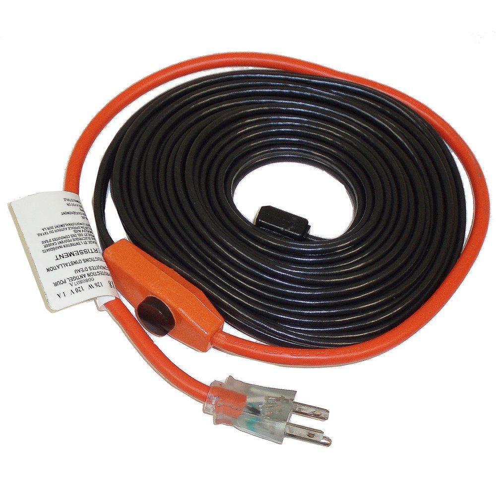
Easyheat Freeze Protection Cable Rona Water Pipes Fiberglass Insulation Frozen Pipes

Easyheat In Line Inside The Pipe Heater

Is Your Process Right For Heat Tracing 2007 01 01 Process Heating

Electrical Heat Tracing Systems Nvent Raychem

208 volts 277 volts 2703 2 75 1 28 2705 2 86 1 16 2708.
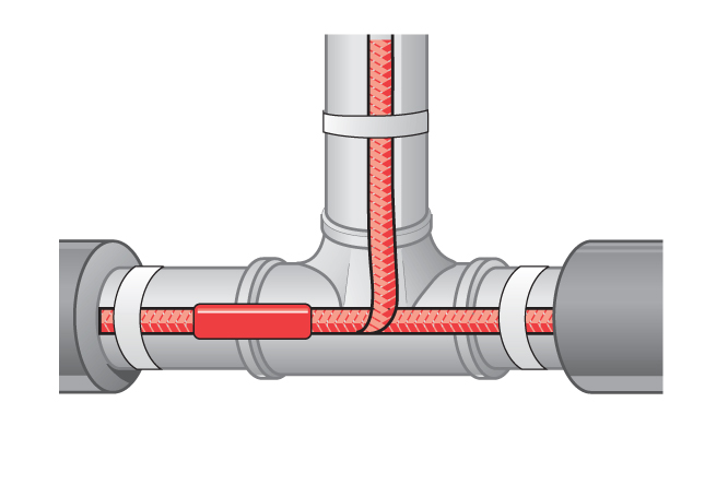
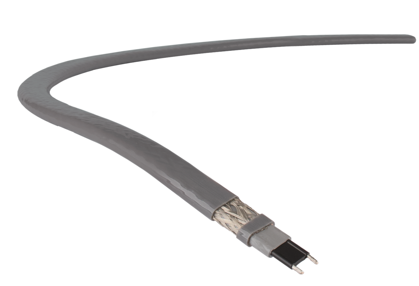
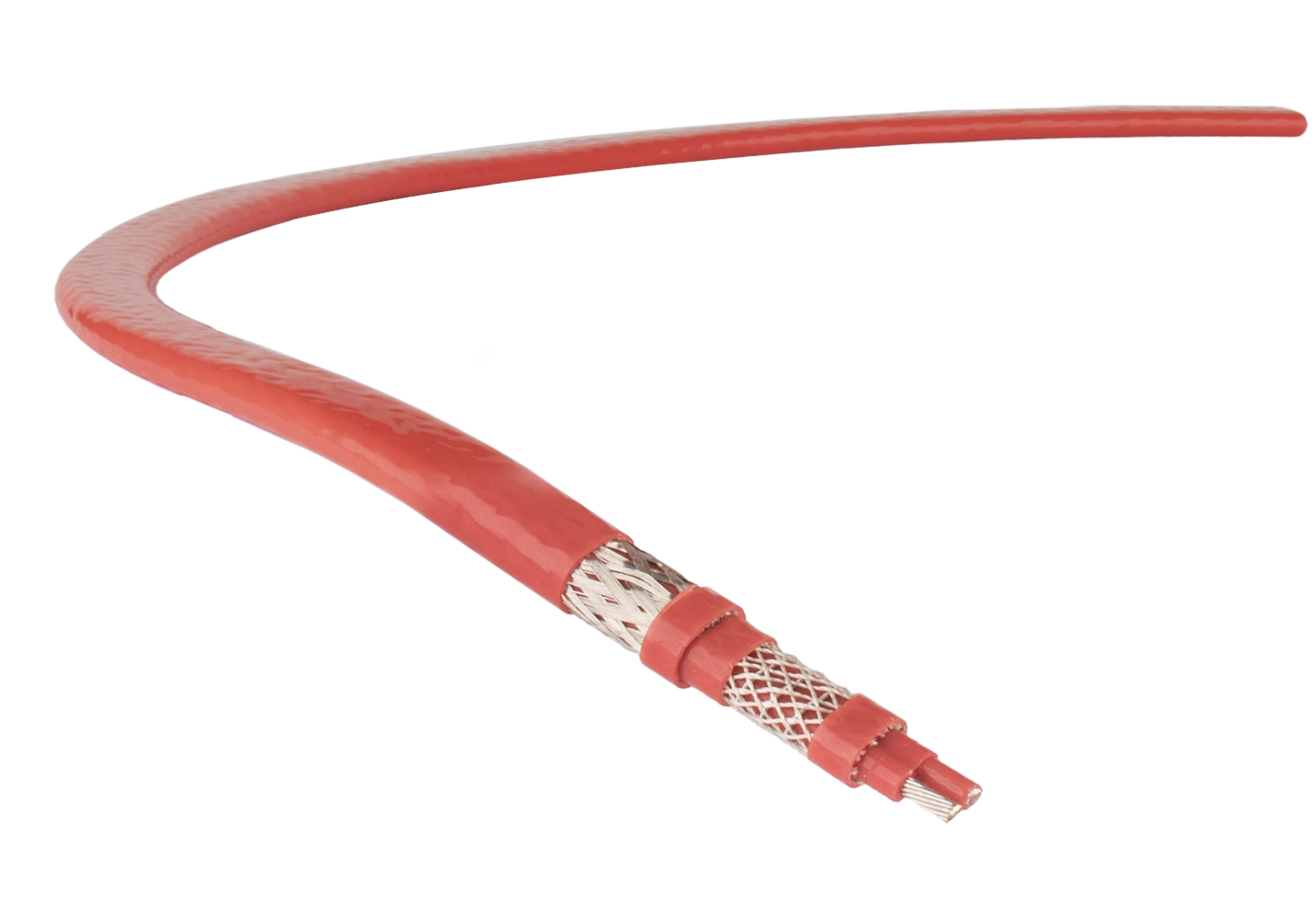
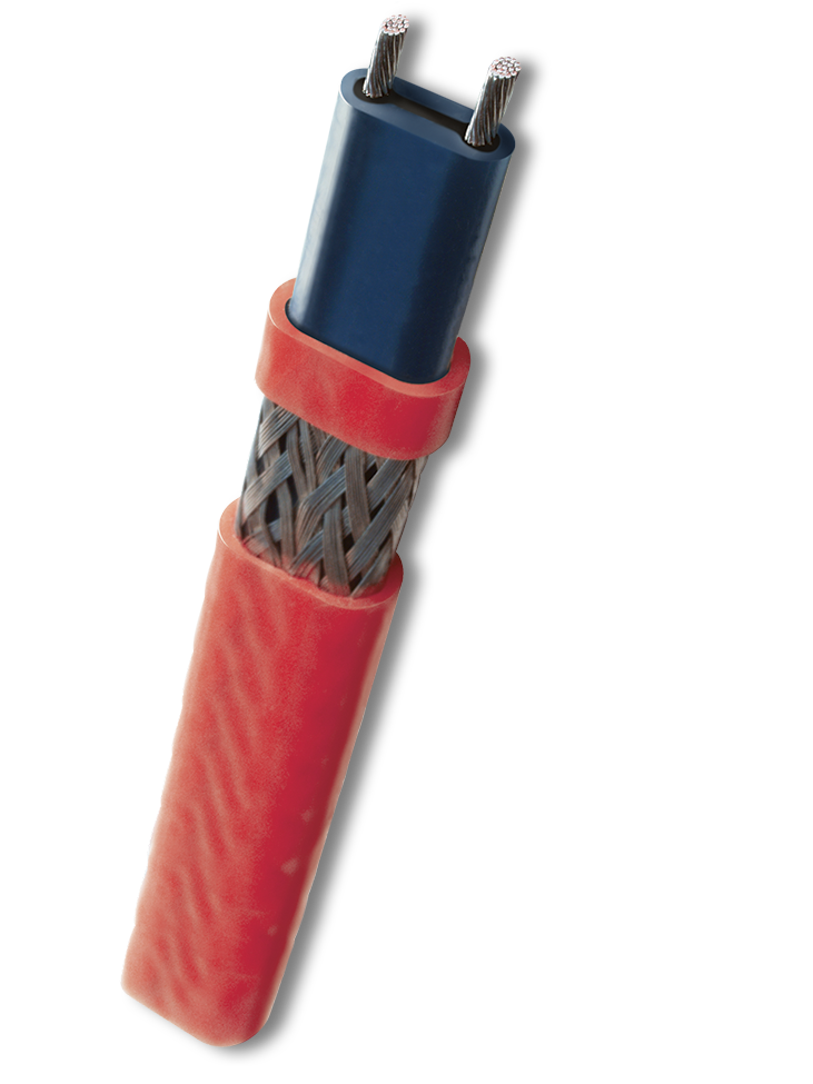
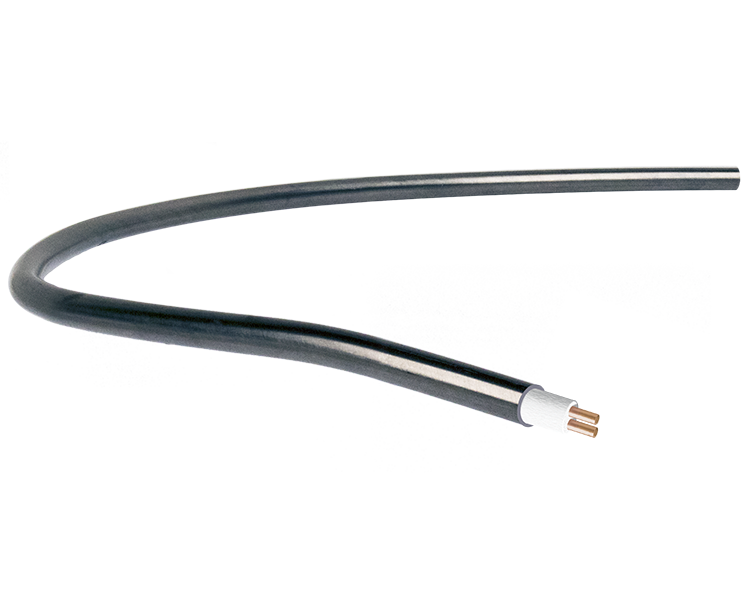
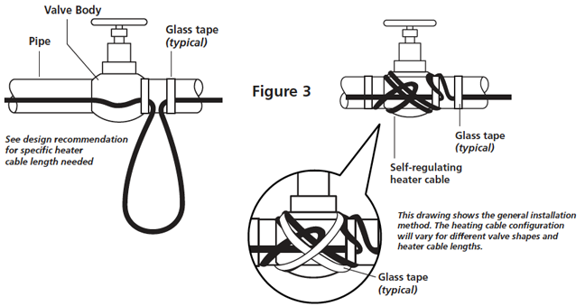
Heat trace cable installation guide. These heat tracing cables consist of a conductive polymer heating matrix extruded between two parallel copper bus conductors. Have been hydrostatically tested prior to the installation of the heating cable. Of heating cable required to efficiently heat trace pipes valves and flanges. Heat trace the demands placed on heat tracing systems vary based on the design parameters specific to each application.
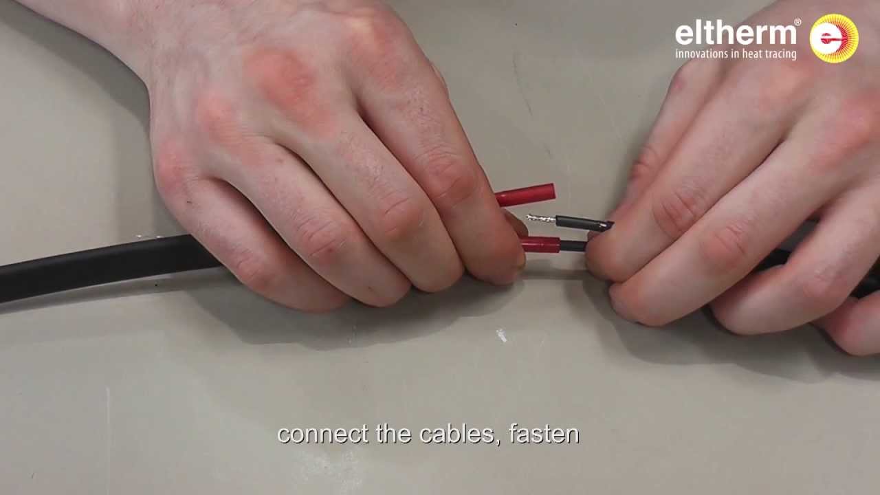
Nvent unveils wireless communication heat tracing solution london business wire nvent electric plc nyse nvt nvent a global leader in electrical connection and protection solutions today announced the launch of the nvent raychem elexant 9200i wireless communications interface. The canadian electrical code requires that all heat tracing applications utilize. To meet these needs thermon manufactures the widest variety of electric heating cables and control systems in the world. Refer to installation instructions included with cable termination kits or contact thermon for specific instructions to fabricate heating cable.
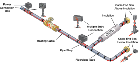
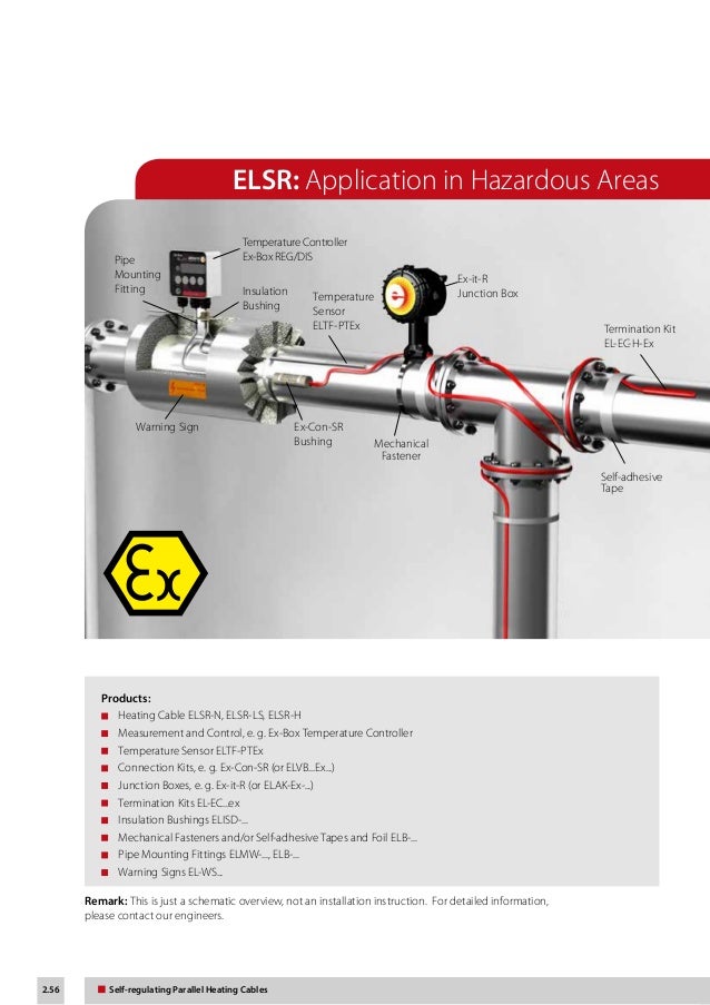
Heat tracing systems comprise heating cables and ancillary items which necessarily interface with other system components such as thermal insulation and the electrical supply items which will power the system. Heat is generated in the conductive. Always install tracing at the 5 or 7 o clock position on a pipe. Sensor location heating cable typical pipe wall.
Walk the system and plan the routing of the heating cable on the pipe. Power adjustment factor part no. Selection of heating cable type and rating should be in accor dance with the procedures located in the chromalox design guide for heat tracing products. Complete the pipe pressure test.
An insulation resistancetest on each reel is recommended. Check piping to be traced. Inspect heating cable and components for in transit damage. Alternate voltages rscc 240 vac self regulatingheating cables can be operated at alternative voltages.
Each heat tracing application imposes unique demands on the designer to achieve the desired performance in a safe manner. The chart below compares heating cable power output with prod uct rating. Termination kits to fabricate a heat tracing circuit are not addressed in detail in these installation procedures.
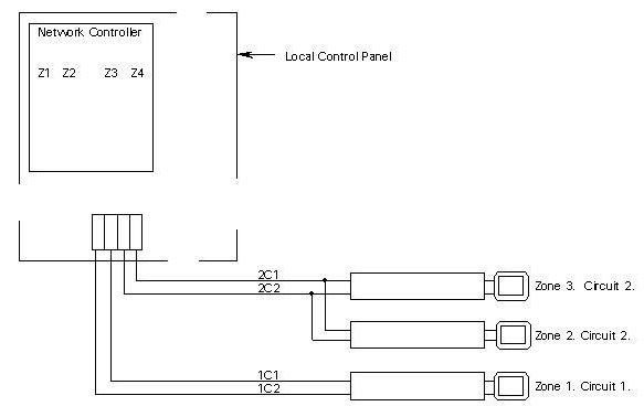
Intech 21 Inc Hccm 2100 Heater Cable Control And Monitoring System Installation Manual Hccm 2100 Addressing Procedure

10 Ways To Use Electric Heat Tracing To Keep Industrial Fluids Flowing In Winter 2009 09 01 Process Heating
Pipe Heat Tracing Solutions Ensure The Prevention Of Freezing Pipes
Https Encrypted Tbn0 Gstatic Com Images Q Tbn 3aand9gcse9e3q4mfew9cr5mrp9qfz74w Bqvgmljk1a Usqp Cau
Rgs Process Heating Solutions

Electric Heat Tracing Installation Procedures Video Youtube

Reduce The Amount Of Pipework Required To Supply The Hot Water By Removing The Need For The Return Part Of A Flow And Retu Heating Systems Heat Mat Hot Water

Pin On Rvs
Hpt Process Heating Solutions

Pipe Heater Pipe Freeze Protection Warmup
Eltherm Self Regulating Heat Trace Cable Product Catalogue

Electrical Heat Tracing System Heat Trace Cable Supermec

Heat Trace Systems For Water Line Freeze Protection Freeze Protection Protect Water Water Pipes
Usx Process Heating Solutions

Self Regulating Cables Heat Trace Cables Trace Heating Cable Eltherm

Himalco Cables Is A Electric Copper Wire Cables And Aluminum Wire Cables Manufacturer From India Product Range Include Single Two Three And Four Core Aluminu
Miq Process Heating Solutions
Introduction To Heat Trace Cable Systems
Https Encrypted Tbn0 Gstatic Com Images Q Tbn 3aand9gcq2qec8nz3oq9m9phztbxjkdnmfeb3gvdrd4svndtyyimd50ea1 Usqp Cau

Easy Heat Adks 1000 Roof Gutter De Icing Cable 200 Cool Roof

Box Of Samples Of High Voltage Underground Cables Electronic Engineering High Voltage Power Cable

Inspection Of Self Regulating And Power Limiting Heating System Cables

Automatic Electric Heat Cable Kits Frost King Products Electricity Cable Heat

Roof And Gutter Heat Cable Kit Ice Dam Prevention Keep Your Roof Gutter And Eaves Free From Ice Dam Formations This Winter Wit Gutter Heaters Gutter
Heating Cable Self Regulating Elsr N Ao Connection 2 Cables Electrical Heat Trace Youtube

How To Install Your Own Central Heating System Heating Systems Central Heating System Central Heating

Trace Heating Direct Heating Systems Heat Telford Shropshire

An Insight On India S Power Cable Manufacturing And The Stand Of Manufacturers In The Present Day Power Cable Cable Wire Power

Raychem Frostguard Self Regulating Heating Cable The Heat Cable Store

Contact Us Heating Systems Telford Shropshire European Standards

Steam Heat Tracing Solution For Every Pipe Temperature From Freeze Protection To High Temperature Process Maintenance Website Htt Computer Repair Repair Steam

Eltherm Elp Pfa Heat Trace Cable Spec Sheet By Thorne And Derrick Uk 44 0 191 490 1547 Via Slideshare
Tyco Raychem Trace Heating Installation Guide

Wrap On Roof And Gutter Heat Trace Cable
Easy Heat Rs2 Automatic Roof De Icing Cable Control In 2020 De Icing Roof Fire Sense

Ep Book Fiber Optic Fiber Internet Fiber Optic Cable

Heat Trace Heater Cable Sealing Kits Industrial Heat Tracing Emerson Us

Drawing Demonstrating Adding A New Junction Box From An Outlet Electrical Cables Home Electrical Wiring Electrical Wiring

Heating Cable Self Regulating Elsr N Bo Power Termination Electrical Heat Trace Youtube

Circuit Breaker Wiring Diagrams Home Electrical Wiring Diy Electrical Electrical Breakers

Custom Designed Radiant Heating Systems From Radiant Engineering

Pin On Warmzone Products